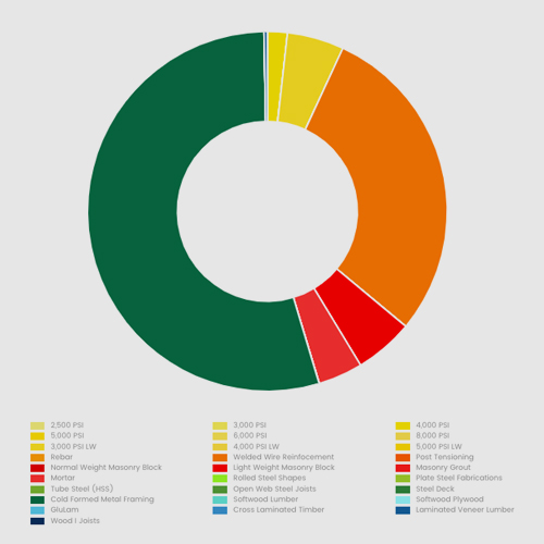
Included on this page are Embodied Carbon Intensity Diagrams (ECIDs) for some typical framing schemes for various building types. The main intent of these diagrams is educational, and to provide a range of embodied carbon values for the analyzed bays to inform the practicing structural engineer of embodied carbon intensity for framing schemes considered typical. These could also be used to back check your own assessments or even as a general guide for early design embodied carbon estimates.
Methodology
- SE 2050 Committee members wrote the design rules for the bays and established the parameters for each bay.
- At least three structural engineers designed each bay.
- Three Life Cycle Analysts each used a different commercially available software to perform LCAs for each of the designs.
- Results (at least 9 LCAs per bay) were compiled and summarized.
Limitations
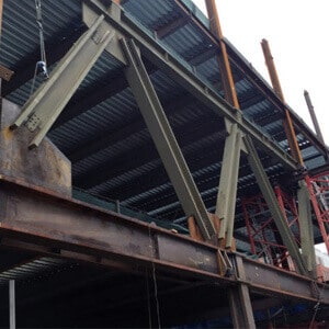
These analyses include only the horizontal framing inside one typical interior bay. Vertical members such as columns are not included. Other elements such as lateral members, foundations, and non-structural elements are not included. These findings are not meant to be extrapolated to full buildings.
ECIDs are for educational purposes only. SE 2050 recognizes that represented bays are not functionally equivalent and therefore direct comparisons between them should not be made. The ECIDs should not be used to compare dislike materials.
