INTRODUCTION
A net-zero carbon future requires structural designs that are smart, well-coordinated, and efficient. This guidance pertains to this design optimization process and structural design decisions which can lead to reduced embodied carbon emissions. For general information on embodied carbon see ‘
What is Embodied Carbon’.
While many design decisions for buildings are outside the control of the structural engineer, there are still a variety of strategies available to reduce the embodied carbon of the structure. It should be recognized that many of these strategies require close collaboration with the project architect and the rest of the project delivery team.
Two primary levers available to structural engineers for reducing embodied carbon include structural material selection and structural material efficiency. Some holistic strategies included here address how these levers could be pulled simultaneously. Other strategies address specific structural material systems. A majority of these strategies involve reducing material use as much as possible, ultimately reducing the carbon emissions involved in production. Lighter structural elements also reduce structural demand, and subsequently structural material, for downstream structural elements.
Note: for the information on this page, design guidance strategies are considered separate from material specification strategies. Refer to the SE2050 specification guidance for information related to procurement strategies for reducing embodied carbon.
References and Resources:
The Engineers & Geoscientists British Columbia published an excellent guide for reducing structural embodied carbon in September 2023.
A 2017 PhD thesis by Dr. Catherine De Wolf includes examples of how designers can reduce the embodied carbon of building structures.
BUILD LESS
Similar to how the health of the economy is tied to overall production, the health of the construction industry in the U.S. is largely measured in terms of new construction starts. Yet from a perspective of reducing environmental impact, we must avoid the instinctive tendency to demolish and build anew wherever possible. Structural engineers are integral partners in enabling the reuse of existing structures.
When working with an existing structure, the structural engineer should evaluate the project goals and engage in an open dialogue about the structure’s capabilities with respect to the proposed design program. The International Existing Building Code (IEBC) defines alteration categories based on the scope of the renovation. Strategic programming can be utilized to minimize the triggering of IEBC thresholds which can necessitate more extreme retrofit requirements.
Avoid over-simplifying assumptions relating to an existing building’s structural materials. If time and budget permit, utilize material probing to establish the in-situ material properties such as strength and stiffness. When strengthening is required, think creatively about how to maximize material and economic efficiency while considering what is feasible to construct within the existing building.
When designing new buildings, the design team must consciously think about the building throughout its lifespan and balance its current needs with future flexibility and adaptability. See “Design for Adaptability and Deconstruction” for additional information.
References:
Nothing is better than something (Source: The Institution of Structural Engineers)
How can we create an engineering industry while building nothing? (Source: The Institution of Structural Engineers)
Future adaptability of steel framing (Source: American Institute of Steel Construction)
Material efficiency: A white paper (Source: Resources, Conservation and Recycling journal)
Buildings that last: Design for adaptability, deconstruction, and reuse (Source: American Institute of Architects)
CARE tool (Source: Architecture 2030)
Assessing the Carbon-Saving Value of Retrofitting vs Demolition and New Construction at the United Nations Headquarters (Source: Vidaris, Inc.)
BUILD SMART: EARLY DESIGN DECISIONS
As illustrated in the figure below, it is critical to evaluate and address structural embodied carbon during the early stages of design, where the most significant opportunity for reduction exists.
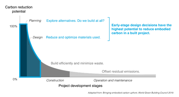
Reference: Bringing Embodied Carbon Up Front (Source: World Green Building Council)
Site Location and Substructure
Basement and foundation structures are typically very carbon-intensive due to the relatively high carbon intensity of concrete and the amount of material required to construct below ground. When establishing a location for new construction, consider the building location relative to site constraints including ground elevations and soil conditions and the resulting impact on basement and/or foundation systems.
Consider limiting basement structures where possible and in particular, basement structures with multiple below-ground levels. For a given site and soil conditions, the carbon intensity (and cost) of basement structures will typically increase with their depth, due to the increased thicknesses of walls etc. required to resist soil and hydrostatic forces.
Ground Floor Advantage
Where possible, work with the architect to locate heavy equipment and specialty systems on lower floor levels in order to reduce the size of the gravity and lateral systems. Similarly, vibration-sensitive spaces (e.g. MRI suites) should be located on ground level where possible, to limit the extent of material-intensive elevated low-vibration structures.
Floor Bay Studies
Many studies point towards the floor system, the building’s major bending system, as the largest contributor to the embodied carbon of the superstructure. Therefore, developing an economical floor system, with efficient span and depth dimensions, is an important step towards reducing embodied carbon. Bay studies should be conducted during early design to discover optimal system options and framing arrangements and communicate these to the project team. Optimal framing typically varies by material system and can be determined through parametric modeling and/or optimization.
Using regular structural grids in floor layouts can result in dramatic savings in embodied carbon. Use standardized bay sizes where possible, which are representative of the bay study recommendations. Avoid non-rectangular bay sizes, which can require additional columns and framing members that a rectangular bay of the same area would not need.
Avoid excessively long-span floor structures and excessive cantilevers where possible, particularly when subjected to high loading or stringent serviceability demands. Excessive spans and cantilevers will increase the embodied carbon (as well as the cost) of a structural system. If these features are necessary for the design, work with the architect to evaluate and minimize the impact on embodied carbon.
References:
Embodied carbon: structural sensitivity study (Source: The Institution of Structural Engineers)
Good early stage design decisions can halve embodied CO2 and lower structural frames’ cost (Source: Structures journal)
Parametric Design Methods
Parametric tools can be a powerful tool in early-stage design to explore and compare design options. These tools can range in complexity, from spreadsheets to parametric CAD tools. For example, a parametric model could be developed with geometric and material variables, and the resulting design space can be explored for options with low embodied carbon. Aside from generating design options, these explorations importantly build understanding on the effects of design decisions on embodied carbon for a specific design problem beyond typical rules of thumb.
References:
Parametric Structural Design for High-Performance Buildings (Source: STRUCTURE Magazine)
Smart Material Selection and Hybrid Structural Systems
While many strategies emphasize reducing structural weight, selection of structural materials during early-stage design also have significant impacts on embodied carbon. It is important to consider different material systems early and evaluate their embodied carbon impacts.
Consider combining structural materials into hybrid systems, such as steel or timber framed structures over a concrete podium, timber floors supported by steel framing; or steel-braced mass timber buildings, to utilize different materials where they are most effective.
Tradeoffs between embodied carbon and material parameters such as mass and structural capacity may not always be intuitive, especially in multi-material systems. Rather than adopt a prescriptive approach to always use a certain material, it can be helpful to make estimates and parametric models to identify project-specific tradeoffs.
References:
Design Guide 37: Hybrid Steel Frames with Wood Floors (Source: American Institute of Steel Construction)
Minimizing embodied carbon in multi-material structural optimization of planar trusses (Source: MIT M.Eng. thesis)
Scaling Low-Carbon Construction Materials (Source: IStructE)
Smart Coordination
When coordinating structural with architectural and MEP designs, it is important to recognize the opportunities for reducing structural material.
Avoid design decisions that will lead to inefficient load paths, such as staggered column plans and material-heavy transfer structures for multi-story buildings.
For the lateral design, consider how the vertical structure will be integrated with the base design layout. Use more efficient systems, such as braced frames in lieu of moment frames, where open column layouts are not explicitly required. Where possible, lateral cores and braced frames should be oriented such that there is flexibility to distribute MEP services without large openings through structure, which may require more structural material.
For floor framing, consider the integration of MEP services by using, for example, castellated beam systems, integrated concrete slabs, or layering your structure to accommodate MEP pathways, all of which can reduce the depth and improve the efficiency of the structure.
For stick-framed buildings, consider utilizing stud walls for gravity support where possible in lieu of introducing supplemental structural framing.
Where possible align concrete curbs, masonry walls, or other heavy elements with structural framing members, to avoid adding new support members. Locate floor openings away from column lines to avoid interrupting girders. These decisions help minimize the need for additional structural material.
Minimize excessive Requests for Information (RFIs), errors based on miscommunication, and rework; all of which add waste and embodied carbon. This can be done by ensuring structural systems are coordinated with other trades and by enhancing the overall clarity of construction documents.
Prefabricated and Offsite Construction
Prefabricated components, systems, and modular units are assembled under controlled conditions using materials that are often ordered from the supplier in exact quantities and dimensions. This typically results in a manufacturing process with more efficient material utilization, which can help to reduce carbon emissions by eliminating waste.
Less than five percent scrap is typical for the fabrication stage of modular construction, which means less processing of virgin materials and less waste material going to landfills. Prefabrication can also result in less site disturbance and thus lower environmental impacts at the job site, while tighter tolerances may create fewer gaps between assemblies, resulting in improved energy efficiency. Specifiers should be cautious about trade-offs which may require more strength and materials to allow for handling and transportation of the prefabricated components.
References:
Life cycle greenhouse gas emissions and energy analysis of prefabricated reusable building modules (Source: Energy and Buildings journal)
Reducing building life cycle carbon emissions through prefabrication: Evidence from and gaps in empirical studies: savings in embodied carbon are possible through prefabrication but quite dependent on the potential for reuse (Source: Building and Environment journal)
Refocusing modern methods of construction on the climate emergency (Source: Institution of Structural Engineers)
Non-Structural Applications
Advocate against the use of carbon-intensive structural materials for non-structural applications, e.g., concrete for partition walls or flooring, where lower carbon options are available. However, dual-purpose structural elements – such as exposed structure that eliminates the need for interior finish – can be beneficial for minimizing embodied carbon at the whole building scale.
EVALUATE DESIGN METHODS
Once the building form and structural systems have been established, the refinement of the structural design is typically conducted according to a basis of design approach, some aspects of which may require engagement with and input from others in the project team.
When developing a basis of design approach, it is important to identify the sensitivity to the different design assumptions and criteria of the resulting design and associated embodied carbon. Doing so will enable key levers to be identified and raised as needed with the external project team, such that reductions to embodied carbon may be realized.
Even when designing buildings per prescriptive building code provisions, engineering judgment plays a role. Code provisions provide load factors to amplify the structural demand and resistance factors to reduce member strength. Often however, serviceability requirements, including deflection and vibration criteria, can govern the design of structural members. In these cases, engineers must use judgment to determine what level of performance is appropriate and what assumptions can be made to refine serviceability criteria and resulting structural design.
Loading
Loading assumptions will directly affect the demand on the building structure and the resulting size of structural elements. Superimposed dead loading assumptions should be coordinated and communicated with the design architect to ensure that these reflect the design team’s and client’s needs.
Minimum live loading for floors is typically established using loading criteria based on occupancy as prescribed by the building code. In some cases, higher live loading criteria may be required by the client to enhance the building performance or future flexibility. In such cases, it is recommended to engage in a dialogue to illustrate the impact of these assumptions on the structural design and embodied carbon such that opportunities for reduction may be realized.
Where non-standard live loading is required, for future flexibility or otherwise, consider whether this can be limited to specific areas of the building, or to specific structural elements (e.g. columns / vertical structure) which are challenging to modify in future and where the impact on whole-building embodied carbon is relatively small. Live load reduction provisions should be utilized where possible, in accordance with building code requirements, to limit the demand on elements supporting large floor areas or multiple floors.
For structures supporting mechanical equipment, consider the specific locations and weights of equipment when establishing loading criteria.
The use of a wind tunnel procedure may provide a basis for reducing wind loads values calculated by standard design procedures. Note that ASCE does not permit a reduction of MWFRS wind loads greater than 20% when using a wind tunnel procedure.
References:
A weight off your mind: floor loadings and the climate emergency (Source: The Institution of Structural Engineers)
Serviceability Criteria
Serviceability criteria, including deflection and vibration requirements, can often control the structural design, particularly for longer-span systems. On this basis, it is important to evaluate the criteria being used for the design, and identify whether the anticipated structural performance (often established via computer models) is realistic.
Take advantage of higher deflection limits for different structural elements as allowed in the building code, e.g. for roof structures or areas without sensitive partitions. Evaluate atypical deflection limits e.g. for facade or elevator systems, and ensure that such limits are fully understood before applying these to the structural design.
When establishing vibration criteria, evaluate the specific requirements and space use. Communicate the impact of these criteria on the structural design to the project team, and evaluate any assumptions being made in analysis models, such as connection or support fixity, which should be as indicative as possible of ‘real’ performance. Note that standard bolted connections which are assumed to be pinned for linear static design can typically be assumed as being fixed for a vibration analysis, in accordance with AISC design guidance.
Where only localized areas of specific vibration performance are required, consider locating these elements in the naturally stiffer areas of the bay, for example near columns, walls, or perimeter spandrels.
For specialty structures, consider dampening as an alternative to stiffening of structural members as a means for controlling vibration effects. In some specialized cases, a performance-based design approach may present an alternate pathway to standard code-applied serviceability limits, such that a more carbon-efficient design may be realized.
Maximize Design Utilization
Studies indicate that structural engineers will typically design to maximum utilization ratios of approximately 0.8, with average utilizations of approximately 0.6. Assuming a linear relationship between utilization and material use, this suggests that structural engineers are designing with significantly more material than necessary.
The application of maximum utilization ratios below 1.0 should be avoided during final design. In particular, be aware of the effect of compounding safety factors and rationalization methods (such as enveloping member demands instead of designing individual members), which may lead to some elements being particularly underutilized.
Consider also, the application of material strengths on a project in relation to embodied carbon. Higher strength may enable significant material savings for heavily loaded members, close to their strength design limit. However, lower strength materials may be more appropriate in cases where serviceability requirements control the design. This tradeoff varies by structural element type and should be evaluated on a case by case basis early in design and as the design progresses.
References:
Rationalisation versus optimisation – getting the balance right in changing times (Source: The Institution of Structural Engineers)
Structural Optimization
Where possible, structural optimization should be used to reduce and minimize the amount of structural material and/or embodied carbon in the project. A variety of methods exist, ranging in accessibility and complexity. The three classical types of structural optimization, which typically target material efficiency, include: size optimization, shape optimization, and topology optimization as described below.
- Size optimization: at the most granular scale, individual framing members (beams or columns) can be optimized to be the most efficient (lightest) section based on design criteria set by the engineer. Many analysis and design programs offer a version of this, via an “optimize” or “auto-select” option within the program. A user can set design criteria holistically for the project, for an area of the building, or individually for specific members. This set of criteria can include minimum/maximum section depth, deflection criteria, vibration performance, maximum utilization ratio, and more.
- Shape optimization: structural components may be shaped to use material where it is most needed. This method can be effective for optimizing the depth of bending elements, such as shaped beams and vaulted floor slabs. Recent research has demonstrated affordability and scalability in shaped concrete floor systems (see References).
- Topology optimization: this type of optimization can be applied at various structural scales (e.g. trusses, beams and floors, wall layout, lateral systems, joint connections). This method determines the topology, or layout, of a minimum-volume structure under given loading, support, and serviceability conditions. The layout may be across a continuum design domain (e.g. for walls, floors, or beams) or a discrete design domain (e.g. for trusses or shear wall layout). Aside from topology, other design parameters such as the size and material of the structure can also be determined from the optimization result; it can thus be effective in earlier stages of design. Software is available to perform topology optimization, such as those from Altair, Dassault Systemes, and Autodesk, Comsol, and Ansys. Even without access to such tools, the ground structure method can be used to manually explore discrete topologies (e.g. selecting a truss topology) for material efficiency. Complex results typically present a challenge for fabrication, but practical results are possible (see References).
Tradeoffs between custom optimized designs and standardized designs may also need to be considered (i.e. the lower-carbon custom solutions may require more time and money to design and/or construct). Anticipating these tradeoffs before a project begins can help enable the future feasibility of lower-carbon design solutions. It’s never too late to start or enhance streamlined optimization workflows.
References:
Minimizing embodied energy of reinforced concrete floor systems in developing countries through shape optimization (Source: Engineering Structures Journal)
Design, fabrication and testing of a prototype, thin-vaulted, unreinforced concrete floor (Source: Engineering Structures Journal)
Connecting architecture and engineering through structural topology optimization (Source: Engineering Structures Journal)
Truss topology optimization of timber–steel structures for reduced embodied carbon design (Source: Engineering Structures Journal)
Refocusing Modern Methods of Construction on the Climate Emergency (Source: IStructE)
Rationalisation Versus Optimisation–Getting the Balance Right in Changing Times (Source: IStructE)
Design for Resiliency
Designing for intense natural disasters, such as seismic events, can lead to high embodied carbon and embodied energy emissions when the required post-disaster renovations are considered. Current code-based design is intended to prevent structural collapse, but at the cost of extensive damage to the building, mainly including non-structural elements. By optimizing a structure to perform in a more resilient way, engineers can mitigate the embodied impacts of any future disasters. Using alternative design methods such as performance based design (PBD) to design a more resilient structure can proactively prevent these emissions (and all related costs as well). However the designer must also weigh the pros and cons of this added embodied carbon upfront, versus adding carbon emissions during a renovation in the future.
Reference:
Seismic Performance Assessment of Buildings (Source: Carbon Leadership Forum)
Application of Typical Details
The use of typical details on design drawings should also be evaluated in relation to embodied carbon. Typical details should be refined on a project basis, such that they are representative of loading and design conditions that will be encountered. The application of typical details to atypical conditions is considered a poor engineering practice that can lead to excessive material use and waste and greater embodied carbon for the structure.
IMPLEMENT CIRCULAR DESIGN PRINCIPLES
Incorporate Salvaged Materials
Salvaged materials generally have a fraction of the embodied carbon of new materials. All the emissions associated with initial production of the materials may be neglected when they are reused, so emissions associated with salvaged materials are usually only related to transportation and refabrication. Constructing with salvaged materials is thus a highly effective carbon-reduction strategy.
If your project site has an existing building that must be removed, it may be possible to extract structural materials from that building for use in the new construction. Supply chains are still developing for salvaged materials. Specifying salvaged materials can help build these markets and improve the supply of these materials.
Components such as steel framing and timber beams are readily reusable and may be readily evaluated for reuse. Steel members can be tested for strength and weldability. Timber members can be graded. Knowing the source and age of the salvaged materials can go a long way towards estimating their strength.
When using salvaged materials, it is helpful to know where the materials came from. Knowing the era and location of the building can provide clues as to the structural properties of the material. In the best of cases, original construction documents might be available which explicitly state the required design properties.
References:
The Use of Salvaged Structural Materials in New Construction
Appendix 5. Evaluation of Existing Structures (Source: AISC 360-22 Specification for Structural Steel Buildings)
Steelwise Article: Reclaimed Structural Steel (Source: American Institute of Steel Construction)
A Grading Protocol for Structural Lumber and Timber in Historic Structures (Source: APT Bulletin: Journal of Preservation Technology)
In Situ Evaluation of the Reference Properties of Structural Timber Members. Use of Available Tools and Information (Source: Advanced Materials Research Journal)
Design for Adaptability and Deconstruction (DfAD)
Buildings are often demolished not because they are worn out, but because they no longer are suitable for their purpose. In some situations, it can even cost less to tear down and reconstruct than to renovate. Designing for adaptability can reduce the future economic incentive to demolish a building when needs change. Designing for deconstruction and reuse increases the chances that materials and components are extracted and incorporated into new construction when the building reaches its end-of-life.
Strategies for adaptability include:
- Open plans that permit flexibility of space usage.
- Structural systems that have reserve strength and stiffness to accommodate different uses, or that can be readily upgraded to carry more load.
Strategies for both adaptability and deconstruction include:
- Simple, transparent structural systems that can be observed and evaluated.
- Independent systems that allow, for example, MEP systems to be upgraded without disturbing the structural system.
- Durable systems.
- Labels on components with strength characteristics (similar to grade stamps on wood framing).
- Clear explanation of design criteria (i.e. loading, deflection criteria, vibration criteria) on the general notes.
- Dry connections and mechanical fasteners, such as bolts and screws, in place of welds and adhesives.
Designers must balance DfAD with design optimization goals. A fully optimized structure designed for light loads may prohibit future adaptation to a use requiring heavier loads. Designing for adaptability and deconstruction will more effectively address long-term climate goals than short-term goals.
References:
Designing Structural Systems for Deconstruction: How to Extend a New Building’s Useful Life and Prevent it from Going to Waste When the End Finally Comes
Future Adaptability (Source: American Institute of Steel Construction)
Deconstructable Systems for Sustainable Design of Steel and Composite Structures (Source: American Institute of Steel Construction)
BUILD LIGHT - STRUCTURAL STEEL
Involve a Local Fabricator Early
One of the most important decisions the project team can make to reduce the environmental impacts of steel-framed structures is to engage a structural steel fabricator early in the design of a project. The fabricator will be able to provide specific suggestions regarding the optimization of the framing system from both a material and fabrication perspective. For example, bay spacing designed at 42 feet may produce unacceptable waste for member sizes standardly available in 40 foot lengths; lighter members may reduce embodied carbon themselves but often require time-consuming and material-heavy stiffening and connections; and fabricators will have different connection preferences based on the unique capabilities of their respective shops. The early involvement of the steel fabricator will help assess the relative tradeoffs of these design decisions to reduce material and waste. If not done during the bid process, do so immediately after.
References:
Project Delivery Methods (Source: American Institute of Steel Construction)
Use High Strength Material
For hot-rolled sections, Grade A992 became the standard grade in 1998 and represented a 40% increase in the strength of structural sections from 36 ksi to 50 ksi. Today, A913 Grade 65 (65 ksi) is produced domestically and is particularly appropriate for large columns and belt trusses. Reduction in material used due to higher strengths has a linear impact on embodied carbon reduction.
References:
Who makes the shapes you need? (Source: American Institute of Steel Construction)
Design Load-Optimized Members
The entire length of a steel beam or a column is not necessarily experiencing the same level of stress. At times a smaller section containing less material can be used if a plate is welded to the beam or column to handle the higher level of stress in a given region of the member. This option should be evaluated carefully in order to balance the effects of reduced member weight and environmental impacts with the additional fabrication labor time and cost.
References:
On Demand Course – Design of Reinforcement for Steel Members: Part 1, Part 2 (Source: American Institute of Steel Construction)
Castellated Beams
Creative fabrication practices can add substantial value to a traditional steel beam. For example, a wide flange beam may be split into two halves, separated, staggered, and welded together to form a castellated beam. The new beam weighs approximately the same but is 40% stronger and 50% deeper than the original beam. This approach provides a substantial functional increase with very little added embodied carbon, particularly when considering that less than 10% of the embodied carbon of a fabricated structural steel member comes from fabrication.
References:
Design Guide 31: Castellated and Cellular Beam Design (video: NASCC 2018 Session) (Source: American Institute of Steel Construction)
Cambering
Floor members can be cambered mechanically, or by heating forces, to deflect the beam in the opposite direction of the deflection from the loading. In some cases, weight and embodied carbon savings as much as 25% can be accomplished. Cambering beams of less than 24 feet in length and cambering of less than ½ inch is not recommended. The use of camber should be discussed with the fabricator and the cost and time tradeoffs should be weighed by the design team.
References:
Design Guide 36 – Design Considerations for Camber (videos: NASCC 2012 Session, NASCC 2021 Session) (Source: American Institute of Steel Construction)
Address Fireproofing
Steel projects often call for cementitious spray fireproofing, which contributes additional embodied carbon, so strategies to reduce and/or replace its use are warranted.
The level of required fireproofing is generally defined according to the construction type classification as defined by IBC chapter 6. Architects can consider pushing for the lowest possible construction type to limit the amount of fireproofing required. They can also limit the shaft locations to fewer bays, for construction types where the shaft openings are driving the extent of fireproofing.
Alternative fireproofing methods to cementitious spray fireproofing are also available, such as intumescent paint and mineral wool board fireproofing. These materials have lower associated embodied carbon emissions, however their use should be weighed against potential cost increases..
As an alternative to structural fire resistance ratings, ASCE 7 sanctions the use of performance-based structural fire design. Notably, ASCE 7-22 Table 1.3-5 now provides applicable reliability targets for structural fire design. This methodology permits synergy between the structural and fireproofing designs/specifications, which can significantly reduce reliance on fireproofing (e.g., allowance for non-uniform application of fireproofing). This is demonstrated in the ASCE Structural Fire Design Guide, which is freely available at the link provided below. Note that the application of performance-based structural fire design typically requires consultation with a building code official and a peer review.
References:
Performance-Based Structural Fire Design (ASCE-SEI)
BUILD LIGHT - CONCRETE
Concrete Floor Systems
The use of reinforced concrete remains a popular construction choice, due to its relatively low cost, flexibility and performance benefits including durability and fire performance. However the amount of material needed in concrete-framed buildings, coupled with the carbon emissions associated with cement production can lead to high overall embodied carbon emissions which should be evaluated carefully.
Typically, the majority of concrete used in concrete-framed buildings is for the floor system, therefore priority should be given to selecting a floor system which will minimize the volume of concrete being used. Since concrete is a relatively heavy material, the self-weight of the floor structure often contributes a significant portion of the overall structural loading. Hence, reducing the volume of concrete being used in the structural floor can also lead to significant reductions to structural loading and corresponding demand and embodied carbon of vertical structural systems including columns and foundations.
References:
Good early stage design decisions can halve embodied CO2 and lower structural frames’ cost: importance of deck selection/complexity on embodied carbon (Source: Structures journal)
Comparing different strategies of minimising embodied carbon in concrete floors: carbon-saving concrete floor system alternatives (Source: Journal of Cleaner Production)
Concrete Strength and Mix Selection
The majority of embodied carbon emissions in concrete are a direct result from the cement production process, meaning concrete with higher levels of cement will generally have higher associated embodied carbon emissions. The use of blended cements and supplementary cementitious materials (SCMs) can be advantageous for reducing the required cement content, as well as improving workability and durability performance. Refer to the SE2050 specification guidance for additional information related to procurement strategies for reducing embodied carbon in concrete.
Over-specifying concrete strength results in increased embodied carbon. Specify only the strength that is required for the design of members. If durability provisions in the code require a higher strength, consider taking advantage of that in design.
The use of lightweight concrete in the design of concrete structures should also be approached with caution. Lightweight concrete mixes can have significantly higher embodied carbon emissions versus normal-weight mixes due to the emissions associated with lightweight aggregates, despite also reducing floor plate dead loads on structure.
Industry-wide (average) EPD and regional benchmarks for concrete can be found on the NRMCA website, which are organized by concrete strength, SCM content and type of aggregate.
NRMCA: Environmental Product Declarations (Source: NRMCA)
Cast-in-Place Concrete
Simple concrete flat slabs can be relatively efficient for low span dimensions and have historically been an attractive option for buildings due to their associated ease and speed of construction. However, for longer span dimensions or higher loading conditions, it is generally advantageous to utilize formwork systems that will increase structural depth and stiffness for a given volume of concrete, such as ribbed slab / joist slab and waffle slab systems. Voided slabs, which use void-formers cast into the concrete slabs, can also be an effective way of increasing the stiffness to weight ratio and reducing embodied carbon of the structural deck.
Post-tensioning (PT) of concrete slabs can also be an effective means for reducing structural depth and associated embodied carbon. During PT construction, a pre-compression is applied to the slab after it has been cast, via a series of tendons and anchorages. When evaluating post-tensioned concrete slab systems, consideration should be given to early strength requirements and the impact of a higher cement content on the overall embodied carbon emissions.
References:
Comparison of embodied carbon in concrete structural systems (Source: MPA The Concrete Centre)
Comparing different strategies of minimising embodied carbon in concrete floors: post-tensioning embodied carbon savings increase with span (Source: Journal of Cleaner Production)
Precast Concrete
With precast concrete construction, the prefabrication of structural floor panels can eliminate the need for temporary formwork systems and reduce waste. Similar to cast-in-place concrete, the use of profiled slabs can be an effective way of increasing the stiffness-to-weight ratio and reducing embodied carbon. An advantage of profiled precast concrete slabs is that they can be constructed without custom temporary formwork systems meaning they are generally much faster to construct than equivalent cast-in-place systems.
Prestressing of precast slabs is also an effective means for reducing structural depth and embodied carbon. Prestressed slabs are typically constructed using high strength prestressing strands cast into floor planks. Using hollow-core planks, with longitudinal voids at the middle of the slab, can also serve to increase the stiffness-to-weight ratio and reduce embodied carbon in precast slabs. Similarly, when evaluating prestressed concrete slab systems, consideration should be given to early strength requirements and the impact of a higher cement content on the overall embodied carbon emissions.
Reinforcing
Steel reinforcing provides an important contribution to the total embodied carbon of reinforced concrete structures and should not be overlooked. In applications controlled by sectional strength, the use of high strength reinforcement can be advantageous for reducing the amount of reinforcement required and total embodied carbon. Doing so can also help to address reinforcement congestion and improve constructability.
The contribution of lap splices and bends to the total reinforcing quantity should also not be overlooked when evaluating the embodied carbon in reinforced concrete structures. The use of mechanical coupling devices can be an effective method for reducing some of this material, which can also help to reduce reinforcement congestion and improve ease of construction.
Concrete Masonry Units (CMU)
When designing with CMU, the use of allowable stress and strength design methods should be prioritized over empirical methods or rules of thumb, to eliminate overdesign. Consideration for material strength can also help to reduce material quantities and embodied carbon. Increasing the specified compressive strength (f’m) may result in smaller reinforcing bars, larger spacing of rebar, reduced wall thickness, and reduced lap splice requirements. Consideration for the prism test method instead of the unit strength method to determine compressive strength can also be advantageous for an efficient design.
Consideration for standard block dimensions is also important for reducing waste in CMU construction. Where possible, masonry wall lengths, openings and reinforcement spacing should follow a standard 8-inch block module to reduce cutting of units and construction waste. BIM software for masonry can assist with design and layout of walls noting these inefficiencies.
BUILD LIGHT - WOOD
Wood Trusses and Pre-Manufactured Wall Panels
Using wood trusses and pre-manufactured wall panels can significantly reduce the quantity of wood needed compared to conventional stick-built framing.
Advanced Framing (Optimum Value Engineering)
Advanced Framing, also known as Optimum Value Engineering, is a lean design approach to stick-built wood framing. These practices include: framing at 24 inches on center, aligning studs with joists and rafters to enable use of single top plates, aligning openings with stud spacing, eliminating or reducing header sizes at non-bearing walls, and eliminating unnecessary framing at wall intersections.
References:
U.S. Department of Energy Advanced House Framing
Energy Start Advanced Wall Framing.
Engineered Wood
While engineered wood products such as Laminated Veneer Lumber (LVL) and wood I-Joists are strong and stiff relative to dimension lumber, the embodied carbon of these products is much higher per pound of material due to the glues and manufacturing processes. Compare the embodied carbon of systems framed with engineered wood and with dimensional lumber in cases where either material could be used.
Mass Timber
The typical application of mass timber is cross-laminated timber (CLT) decks supported by glue-laminated (glulam) beams and columns. Column grids should be optimized to maximize CLT deck spans while minimizing beam spans. Column transfers and excessive cantilevers should be avoided as these may require unreasonable member sizes or the introduction of additional framing.
Early participation in the design process by a timber fabricator will allow for member and connection optimization based on the fabricator’s particular experience and capabilities. Coordination with mechanical distribution systems is often a critical step in optimizing the system design.
Alternatives to concrete topping, such as raised floor systems or gypcrete, should be considered to reduce embodied carbon depending on fire rating requirements, sound attenuation, and architectural acceptability.
References:
Mass Timber Design Manual, Vol. 2 (Source: WoodWorks)
Design Materials to Work Together
Floor sheathing adds strength and stiffness to floor joists which may allow designers to reduce joist sizes. The shear flow between the sheathing and the joists must be checked and the fasteners designed to resist the shear force. Wood I-joist manufacturers frequently publish span values that account for this composite behavior. Consider taking advantage of this extra strength in all joist designs.
Aiming for Material Efficiency Regardless of Sequestration
Bio-based materials have the ability to sequester a portion of a tree’s biogenic carbon for temporary periods of time, but this does not mean that buildings should use higher quantities of timber. Rather, the overarching approach of using less material still applies.
References:
Timber and carbon sequestration (Source: The Institution of Structural Engineers)
Custom Sections
The digital manufacturing of mass timber elements offers an opportunity to produce custom structural elements that achieve material efficiency. Some examples of simple customized geometries include arched and tapered elements.
References:
Richmond Olympic Oval (Source: naturally:wood)
BUILD LIGHT - CONCRETE AND CLAY MASONRY
Use Masonry Partitions to Resist Structural Loads
Masonry walls are often used as non-structural partitions. When designing structures with masonry cross-walls at regular intervals, consider engaging these walls structurally to provide both gravity and lateral support and eliminate the need for a separate, independent structural system.
Avoid using fully grouted walls unless there are structural or performance reasons to do so. Partially grouted masonry walls, where grout is only placed where vertical or horizontal reinforcing is located, can be used in lieu of fully grouted masonry walls in many applications, and by reducing weight also reduce footing sizes and demands on other structural elements supporting them. The use of reduced weight CMU should also be approached with caution. Lighter weight CMU block can have higher embodied carbon emissions versus normal weight block due to the emissions associated with lightweight aggregates, despite also reducing dead loads on structure. The designer should verify that partially grouted walls satisfy structural and non-structural performance requirements.
Partition walls in buildings don’t always need to be reinforced and can often span as an unreinforced masonry wall (with appropriate joint reinforcement for crack control). Trade-offs between the added embodied carbon of greater wall thicknesses versus reinforcement should be considered on a case-by-case basis.
Consider introducing steel bracing and additional fixity at the top and bottom of tall unbraced masonry walls to reduce structural demands on them. Trade-offs between the added embodied carbon of miscellaneous steel and connections versus the unbraced masonry wall design should be considered on a case-by-case basis.
Modular dimensioning
Design masonry walls and openings on an 8” module to reduce cutting of units and construction waste. For example, instead of designing a 5’-0” wide opening, make it 5’-4” to fall on the module and eliminate the cutting that would be required. BIM software for masonry can assist with design and layout of walls noting these inefficiencies. Opening sizes will need to be coordinated with the architect.
Consider coordinating bond beam spacing that aligns with regularly occurring connections and wall openings to optimize reinforcement.
References: Building Information Modeling for Masonry Resources (Source: The Masonry Society)
Masonry Strength and Materials
The size and spacing of masonry and its elements are dictated by the compressive strength of the masonry (f’m). The most recent masonry design codes (TMS 402/602-13 and later) use a default minimum compressive strength, f’m of 2,000 psi. The use of previous code revisions (TMS 402/602-11 and earlier) should be avoided, which use a lower default minimum compressive strength of 1,500 psi.
Consider specifying strengths that are higher than the default of 2,000 psi depending on local availability of materials. A higher f’m may result in larger spacing of rebar, reduced wall thickness, less grout, and reduced lap splice requirements. While there may be a trade-off of higher EC for higher strength, a thinner wall with less grout and rebar may compensate for the higher cement content. This should be verified on a case-by-case basis.
Use current allowable stress and strength design methods instead of using empirical methods or rules of thumb to design masonry to eliminate overdesign. Consider using the prism test method instead of the unit strength method to determine masonry’s f’m as that will also result in a more efficient design.
The use of blended cements and supplementary cementitious materials (SCMs) in the mortar, grout, and/or concrete block can help to reduce the required cement content and resulting embodied carbon impact of masonry construction. Refer to the SE2050 specification guidance for additional information related to procurement strategies for reducing embodied carbon in concrete masonry units (CMU).
BE INQUISTIVE!
The successful implementation of these design principles requires embodied carbon considerations to be placed at the forefront of the design process. During early design, use empirical data and rules of thumb to drive decision making on the ‘big-ticket’ items impacting embodied carbon (e.g. building reuse and programming) and prioritize improvements to those items before refining structural systems. Be ambitious and advocate for the use of embodied carbon metrics in decision making, such that reduction strategies may be successfully implemented.
During design, continue to estimate and evaluate embodied carbon and use those estimates to inform the design process. Do not be daunted by the uncertainty of the estimates, which are typically good enough to understand the relative impact of high-level design decisions; the design stages that provide the certainty needed for a full LCA typically come too late to make impactful decisions. Explore design options and use their relative embodied carbon performance to drive decisions. These explorations can range from simple comparisons between a few designs to more detailed parametric models.
Open a collaborative dialogue and host embodied carbon workshops to identify the reduction opportunities which are specific to your project. Be transparent by including embodied carbon information on design documentation.
Lastly, rapid progress towards a sustainable construction industry will only be possible if we share our knowledge and lessons learnt around issues of embodied carbon. This can be done within your organization as well as within the SE 2050 community!
References:
Bringing Embodied Carbon Upfront (Source: World Green Building Council)
Parametric Structural Design for High-Performance Buildings (Source: STRUCTURE Magazine)
Persuasion and Influence in a Climate Emergency (Source: Institution of Structural Engineers)
ACKNOWLEDGEMENTS
Thank you to the following for your contributions to this document.
- Fraser Reid, Buro Happold
- Mark Webster, SGH
- Charlotte Sauer, Thornton Tomasetti
- Max Puchtel, American Institute of Steel Construction
- Julia Hogroian, SGH
- Demi Fang, MIT